


WingEd
WingEd is a (work in progress) 3D modeling tool focused on game dev and low-poly level design / prototyping. Its interface is inspired by SketchUp, Hammer 2, and Doom Builder.
WingEd works on Windows only. Download latest build (unstable, for testing only!)
Technical Details
WingEd only operates on closed manifold surfaces. Internally it uses the half-edge data structure to represent meshes.
WingEd makes use of persistent data structures to store editor state, using the immer library. This allows for simple and robust implementation of undo, and rollback after errors. In the future it could help with adding concurrency.
Interface Documentation
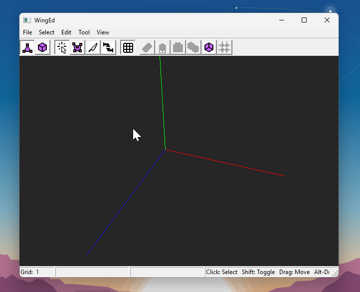
Selecting any tool or hovering over any menu item will show help text in the status bar. All keyboard shortcuts can be found in the menus.
View
Drag with the right mouse button to orbit the camera. Drag with the middle button to pan. Scroll to zoom in/out, or hold Shift and middle-drag to move the camera forward/back.
The View menu includes toggles for Wireframe mode, orthographic views, and first-person perspective.
You can also create multiple viewports, allowing you to view the model from multiple angles simultaneously.
Selection
There are two selection modes: Elements, for selecting vertices, edges, and faces, and Solids for selecting closed solid surfaces.
Tools
These can be selected in the toolbar or the Tool menu.
Select
Left-click an object to select. Hold Shift to select multiple.
The Select tool is also used to move objects. Click and drag anywhere to move objects along an axis-aligned plane. Holding Shift will constrain movement to a single axis, and holding Ctrl will move forward/backward (perpendicular to the plane).
Hold Alt and drag to move objects along the selected face plane.
By default movement is snapped to a grid. You can use the [ and ] shortcuts to quickly adjust the grid size, or press G to toggle the grid on/off.
Polygon
The Polygon tool is used to create new double-sided planes by drawing the points of a polygon. Points are drawn on the plane of the last face that you selected.
Click to place a new point, press Backspace to delete the last point. After drawing a shape, click the first point again to complete the polygon.
Once your polygon is created, you will likely want to extrude it.
Knife
The Knife tool is used to create vertices and edges. You can split an edge with a vertex by clicking it, or carve edges into a face by clicking vertices in sequence.
Once you click a vertex, the knife stays attached to that vertex so you can draw edges connected to it. Press Escape to complete the drawing.
There are a couple rules to keep in mind:
- Faces cannot contain holes, therefore if you want to carve a hole into a face, it must have a “bridge” edge connecting it to the outer loop.
- Similarly, you cannot start drawing in the middle of a face, you have to begin with a vertex or edge.
- The Knife uses the most recent face you hovered over to determine where to carve edges. This is highlighted in the editor.
Join
The Join tool is used to remove vertices, edges, or faces, by gluing them together.
With a single vertex/edge/face selected, switch to the Join tool and click another one to join them. Or, click them both in sequence while in the Join tool.
Edges and vertices must share a face to be joined. Like the Knife tool, the last hovered face is used.
Joining faces is the reverse of the Split Edge Loop operation – it will connect two edge loops together and remove the opposing faces.
Operations
These are all available in the Edit menu.
Erase
In Elements mode, erase selected vertices/edges and join neighboring edges/faces. In Solids mode, delete any selected solids.
Extrude Face
Extrude the selected face by creating faces surrounding its edges. The face will flash to show something happened, but you won’t see the results until you move it. (Hold Ctrl+Alt to move perpendicular to the face.)
If you also select some subset of the edges surrounding the face, only those edges will be extruded.
Split Edge Loop
You must select a continuous loop of coplanar edges. This operation will create opposing faces from the edges, and can be used to split a solid surface in two.
Duplicate
Duplicate selected solids (requires Solid mode). The copies will be created at the same position, so they won’t be visible until you move them.
Flip Normals
Reverse the direction of faces, either for selected solids or the entire model. This can be used to build interior spaces (flipping the normals of a box will create a room).
Snap Vertices
Align all vertices to the grid.
Transform Matrix
This opens a dialog for you to enter a 3x3 affine matrix for more complex transformations. Objects are transformed around the median point.